When the home automation bug bit, the first project I set my sights on was to wire up my ET DC Blue Advanced garage door opener with the Sonoff DC12V/5-32V Wireless WiFi Smart Switch. Read that blog here. After successfully getting that working, the next target was my ET 500 Residential Sliding Gate Motor. I figured that this would be a great way to let people into my property even if I was sitting on the opposite end of the globe. Or use it as a backup in case I needed to open the gate and didn’t have my gate remote.
Disclaimer: I am not an electrician and if you are not one either then you should get your electrician to carry out all steps of this installation.
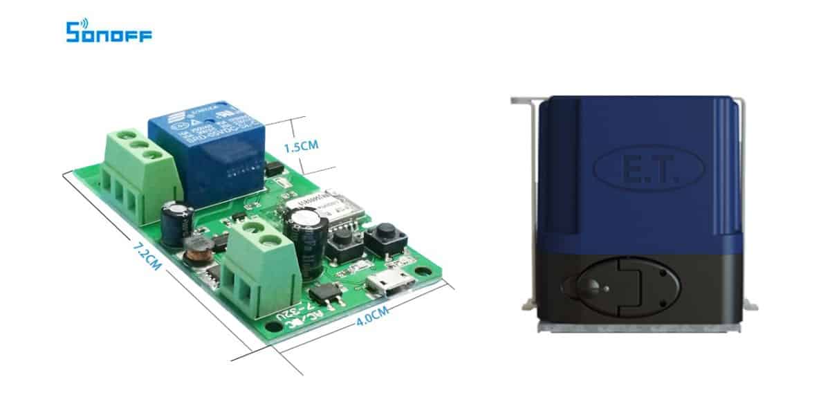
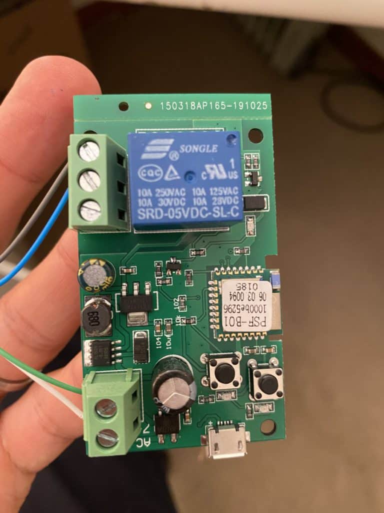
The Sonoff DC12V/5-32V Wireless WiFi Smart Switch is the perfect because it supports inching (more on that later), it can be powered by 5V USB mini or a 7V to 32V DC supply and the relay switch can switch a variety of different voltages. From what I understand, the relay is rated for AC:90 – 250V and DC:0 – 30V. These voltages seem to be confirmed by the text on the blue relay but you should probably double check this. I got mine of Amazon here.
I am now going to take you through the steps that I took to wire the Sonoff DC12V/5-32V Wireless WiFi Smart Switch to my ET 500 Residential Sliding Gate Motor.
Step 1
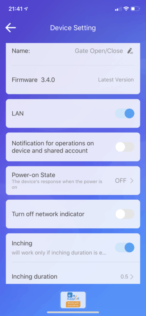
Before you connect your Sonoff switch to your gate motor it is probably best to pair the switch with the eWeLink app. That way you won’t have to do any troubleshooting sitting outside next to your gate! Next you can name the Sonoff switch and make sure that Inching in turned on. Inching with make the Sonoff switch turn on and then automatically turn off after a predefined amount of time. In this case, you can set the Inching duration to 0.5 seconds. This will correctly trigger your ET 500 Residential Sliding Gate Motor to open your gate in the same way your gate remote would open it.
Step 2
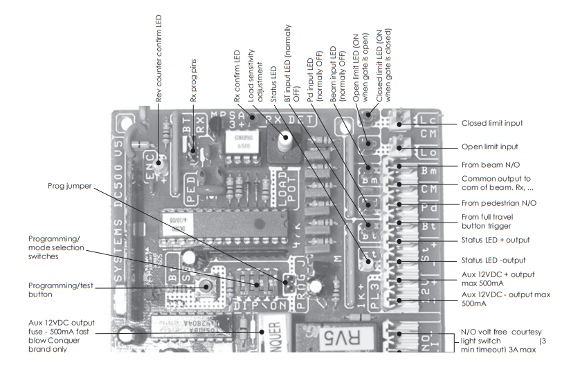
The second step involves reviewing the manual and specifically the wiring diagram for the ET 500 Plus gate motor. You can view the full ET 500 Plus installation manual here.
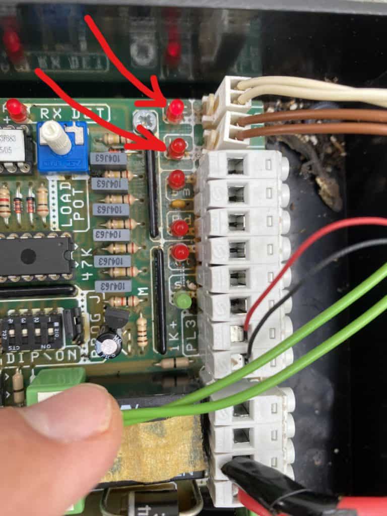
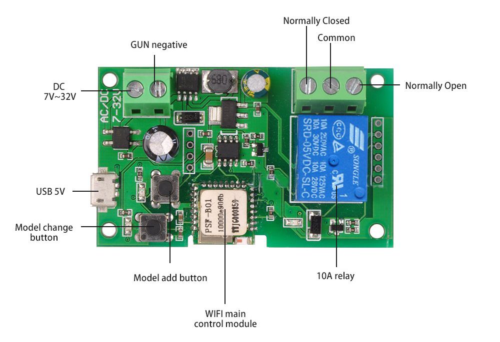
From the diagram below, you can see that the Sonoff switch should be wired up to the relevant connectors on the ET 500 board. So the ‘Normally Open’ terminal of the Sonoff would be wired to the BT connector on the gate motor and the ‘Common’ terminal of the Sonoff to the CM terminal on the gate motor.
Step 3
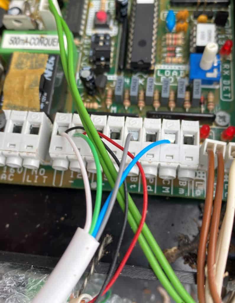
As the Sonoff switch can be powered by a 7V to 32V DC supply, I wired it up to the gate motor’s 12V DC power supply. That way it will be powered by the gate motor’s 12V battery if the power cut or a switch tripped. The gate motors 12V terminals (white & blue wires in above photo) should be wired to the respective positive and negative terminals on the Sonoff. Looks like I wired these incorrectly on mine but it still worked fine. See the labelled Sonoff diagram at the top of the article for reference.
Notes
As you can see below, I wired the Sonoff to the gate motor with light telephone cabling. From what I understand, they will not be carrying much current in this setup.
Home Assistant
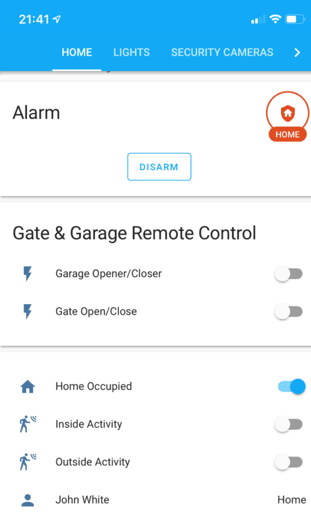
You can just stick to using Sonoff’s eWeLink app to control the gate opener and this works really well. I however decided to begin my journey with Home Assistant so I integrated the switch into my Home Assistant setup.
Rather than flashing the Sonoff switch with Tasmota, I managed to get integrated by using the Sonoff LAN integration found on the HACS (Home Assistant Community Store). This allows me to control all my Sonoff devices on my LAN with Home Assistant. This solution does not require an internet connection as communication is directly with the Sonoff device rather than via the eWeLink servers 🙂
Future Improvements
When I was wiring the Sonoff to the gate motor, I noticed that the ET 500 is aware of the open/close state of the gate using two magnetic sensors. These two sensors are wired into the board using the white and brown wires at the top of the board. They are labelled on the board as LC (closed position) for the white wire and LO (open position) for the brown wire.
If anyone has any idea on how these could be hooked up to home assistant, please drop me a message.